
Currently Empty: ₹0.00

On Sale!
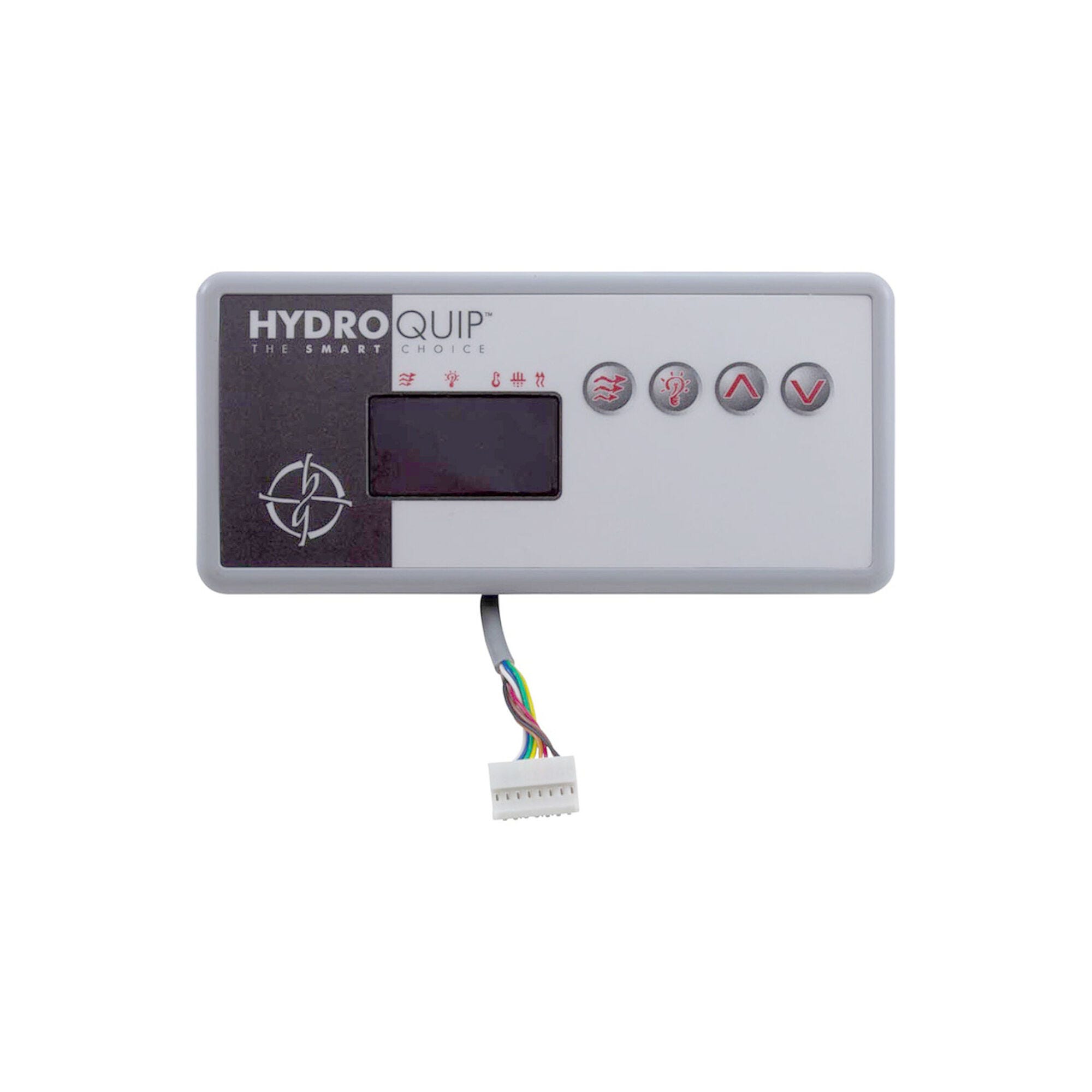
�� Balboa EL2000 Mach 1 Spa Circuit Board — PCB 52680 (Chip EL2000R1B) — Multi-Pump 240V ML-Series Control System Genuine Balboa EL2000 replacement PCB — restore your ML-series spa to full operation. �� Product Overview The Balboa EL2000 Mach 1 circuit board (OEM Part Number 52680, Chip EL2000R1B, PCB PN 22896 Rev B) is the original generation of Balboa’s EL2000 Mach series spa control PCB. Designed for the EL2000 Mach 1 (ML Series) control system, this board manages a high-feature spa configuration including a two-speed primary pump, a second pump or blower, a dedicated circulation pump, ozone generator, spa lighting, and a stereo/audio-visual output — all from a single main PCB. The EL2000 platform was used across a wide range of hot tub brands and models through the late 1990s and 2000s. Spas originally equipped with the EL2000 Mach 1 system can be identified by the chip number EL2000R1B printed on a white label near the center of the existing circuit board. This board is compatible exclusively with Balboa ML-series digital topside panels (ML400, ML700, ML900). The 52680 uses dual DIP switchbanks (A and B) and requires a Persistent Memory reset (A12) any time DIP switch or configuration changes are made — a critical step unique to the EL-series platform. Optional expander boards (X-B, X-P, X-P632, X-P231) enable additional pump and equipment outputs beyond the base configuration. ✨ Key Features ✅ Genuine Balboa Water Group OEM PCB — original equipment board, Chip EL2000R1B, PCB PN 22896 Rev B ✅ Two-Speed Pump 1 Control — 240V main jet pump with high and low speed ✅ Pump 2 Output — 240V, configurable for 2-speed or 1-speed operation via DIP switch B1/B2 ✅ Blower Output — 240V, 1-speed, enabled via DIP switch B3 ✅ Circulation Pump Output — 240V, separate relay, with four programmable filtration cycle modes (A9/A10 table) ✅ Ozone Generator Output — 120V or 240V field-selectable via W13 jumper wire; runs with Pump 1 Low or circ pump depending on A11 setting ✅ Spa Light Output — 12V or 120V selectable via J37 jumper and W9 wire ✅ Audio-Visual (Stereo) Output — 120V at J4, always-hot (no relay) ✅ 5.5kW Heater Support — 240V flow-through heater at full output ✅ Expander Board Support — X-B (blower), X-P (1-speed Pump 3/4), X-P632 (2-speed Pump 3), X-P231 (high-amp branch circuit) ✅ Dual DIP Switchbanks — Switchbank A (12 positions) and Switchbank B (6 positions) for full system configuration ✅ Persistent Memory — Stores all user preferences, filter settings, set temperature, and heat mode without a battery ✅ Real Time Clock (RTC) Support — J91 jumper enables/disables time-keeping for time-capable ML-series panels ✅ Dolphin Remote Compatible — Full-Feature and Spa-Only Dolphin Remote module support (J20) ✅ Made in the USA — Balboa Instruments, Inc. �� Technical Specifications Specification Value OEM Part Number 52680 Chip Number EL2000R1B PCB Part Number 22896 Rev B Base PCBA Part Number 53834-02 (Mach 3 equivalent: 53834-05) System Model E2P-EL2000M3-YCAH Board Type Main Spa Control PCB — EL2000 Mach 1 Board Generation Mach 1 (legacy; Mach 3 = 53834-05) Input Voltage 240VAC / 60Hz Service Required 48A, Class A GFCI-protected, 4-wire (Hot, Hot, Neutral, Ground) Max Breaker Rating 60A Heater Output 5.5kW @ 240VAC Pump 1 Output 240V, 2-Speed Pump 2 Output 240V, configurable 2-Speed or 1-Speed (DIP B1/B2) Blower Output 240V, 1-Speed (DIP B3) Circ Pump Output 240V, 1-Speed, separate relay (DIP A9/A10) Ozone Output 120V or 240V field-selectable at J9 via W13 wire Spa Light Output 12V or 120V selectable at J12 via J37 jumper and W9 AV / Stereo Output 120V, always-hot, J4 DIP Switches Switchbank A: 12 positions (A1–A12); Switchbank B: 6 positions (B1–B6) Fuse (F5 / F6) Class G 30A (two fuses) Fuse (logic) 0.3A 250V Fuse (F10A) 10A 250V Additional Fuse 3A 250V TB1 Torque 27–30 in. lbs. Wire Type Copper conductors only Enclosure Compatibility Plastic Balboa spa pack enclosure ONLY — NOT for metal enclosure Status Discontinued (legacy) — available while stock lasts Warranty 1 year (manufacturer) ⚠️ Heater wattage note: The 5.5kW rating applies at 240VAC. When running at 120VAC, output is approximately 1/4 of the 240VAC rated wattage. ℹ️ US Voltage Note: This board is designed for 240VAC/60Hz US residential service. Do not connect to 50Hz or CE-market power systems. �� Compatibility Guide ⚠️ IDENTIFY BY CHIP NUMBER: Always identify your existing board by the chip number on the white label affixed near the center of the circuit board — not by board appearance. This board is the EL2000 Mach 1, chip EL2000R1B. Compatible Topside Panels (ML Series only): Panel Part Number Panel Name Capability J91 Jumper Setting 52684 ML400 Non-time capable ON (both pins jumpered) 52649-01 ML700 Time capable OFF (1 pin only) 52654-01 ML900 Time capable OFF (1 pin only) ⚠️ The EL2000 board is NOT compatible with VS-series (ML260, ML240, etc.) topsides. ML-series panels only. Compatible Expander Boards (for additional outputs): Expander PN Model Function 53310 X-B Adds 1-speed Blower output when Pump 2 at J5 is 2-speed; W15 to J98 53544 X-P Adds 1-speed Pump 3 output when Pump 2 is 1-speed and Blower is on J3; W15 to J97 53680 X-P632 Adds 2-speed Pump 3 output when Pump 2 is 2-speed; connects to Black AC on main PCBA 53681 X-P231 Branch circuit protection for high-amperage devices; connects to Black AC 53426 X-O3 Dedicated ozone output; used with X-FOW fiber optic kit (adapter PN 25338) 53933 X-Mount P Mounting kit for expander boards in plastic enclosure Replaces / Cross-Reference Part Numbers: Part Number Description 52680 This board — EL2000 Mach 1 PCB (EL2000R1B) 52848 EL2000 earlier variant 52868 EL2000 variant 52487 EL2000 variant BC2003 EL2000 equivalent 33-0029-K Hydroquip EL2000/8000B equivalent 9710-109 OEM variant 59-138-1016 Horizon distributor number for this board Current Modern Replacement Options: Part Number Description Notes 53834-05 Balboa EL2000 Mach 3 PCB Like-for-like PCB replacement; uses same ML-series panels 59003 Balboa EL2000 Mach 2.1 (M2) PCB Compatible replacement; same ML-series panels ⚠️ Note on Mach 3 replacement (53834-05): The mounting hole positions differ between Mach 1 (chip EL2000R1B / TS2000R1A) and Mach 3 (chip TS2000R2A) boards. Verify your enclosure standoff positions before installing a Mach 3 board. ��️ Board Functions & Controls Pump Configuration: Output Connector Voltage Configuration Pump 1 J1 W1 240V 2-Speed Pump 2 J5 W12 240V 2-Speed (B1 OFF, B2 ON) or 1-Speed (B1 ON, B2 ON) Blower J3 W2 240V 1-Speed (B3 ON); W15 to J97 or J98 per configuration Pump 3 Via X-P or X-P632 240V Requires expander board Circ Pump J2 W7 120V or 240V Separate relay — modes via A9/A10 Circ Pump Behavior (A9/A10 Table): A9 A10 Circ Pump Mode OFF OFF No Circ Pump (or not plumbed with heater) ON OFF 24 Hours OFF ON 24 Hr with 3°F Shut-Off ON ON Acts like Pump 1 Low (filter cycles, polls) Heater & Sensor Control: Feature Specification Heater Output 5.5kW @ 240VAC Heater Connectors HTR1 / HTR2 Hi-Limit Sensor Sensor A (SENS. A) Temperature Sensor Sensor B (SENS. B) Pressure Switch / VAC VAC input connector Additional Outputs: Output Connector Voltage Notes Ozone J9 W13 120V or 240V W13 sets voltage — Red AC=240V, White AC=120V Spa Light J12 W9 J37 12V or 120V J37 pins 1–2 = 120V; pins 2–3 = 12V; W9 must match AV / Stereo J4 W8 120V Always-hot (no relay) Fiber / Color Wheel J12 or J2 — Via B4 ON; X-FOW kit may be required DIP Switchbank A (A1–A12): Switch OFF Position ON Position A1 Test Mode OFF (normal) Test Mode ON — technician only A2 Low Amp — heater disabled while any HS pump/blower runs High Amp — heater runs with any HS pump/blower A3 Filter cycles by start/end times (time-capable panels) Filter cycles by duration (non-time capable panels) A4* 12-hour time display 24-hour time display A5* Temperature in Fahrenheit Temperature in Celsius A6 15-min timeout (2 hr for P1 Low) 30-min timeout (4 hr for P1 Low) A7 No Cleanup Cycle Cleanup Cycle ON — 30 min after use; P1 Low Ozone run 1 hr A8 No ozone suppression Ozone suppressed for 1 hr after pump/blower press A9 See Circ Pump Table See Circ Pump Table A10 See Circ Pump Table See Circ Pump Table A11 Non-circ: Ozone ON with P1 Low; Circ: Ozone ON with circ pump (P1 2-speed) Non-circ: Ozone ON in filter/cleanup cycles only; Circ: Ozone ON with circ pump (P1 1-speed) A12 Persistent Memory Retained (normal) Persistent Memory RESET — used at power-up only *A4 and A5 set defaults only when A12 is ON at power-up (persistent memory reset) DIP Switchbank B (B1–B6): Switch OFF Position ON Position B1 Pump 2: 2-Speed Pump 2: 1-Speed B2 Pump 2: Disabled Pump 2: Enabled B3 Blower: Disabled Blower: Enabled (with Pump 2 low relay) B4 Spa Light enabled (J12) Fiber Optic and Color Wheel instead of Spa Light B5 Pump 3: Disabled Pump 3: Enabled (Jets 3 replaces Blower on Aux panel) B6 Normal panel layout Alternate panel layout (ML900 scrunching / ML550/700 Jets 3 replaces Blower) Key Jumpers: Jumper Function J37 Spa Light voltage: pins 1–2 = 120VAC; pins 2–3 = 12VAC. W9 must be set to the same voltage. J91 Real Time Clock: 1 pin only = RTC Enabled (time-capable panels); pins 1–2 jumpered = RTC Disabled (non-time panels) J83 (CFG) Logic Jumper: when NOT installed, DIP switches are active. When installed, locks configuration. W13 Ozone voltage: connects to Red AC for 240V ozone; connects to White AC for 120V ozone W9 Spa Light voltage on second leg of J12; must match J37 setting ⚙️ Installation Requirements ⚠️ IMPORTANT: Installation must be performed by a licensed electrician in full compliance with NEC (National Electrical Code) and all applicable local codes. Pre-Installation Checklist: [ ] Confirm chip number on your existing board is EL2000R1B — check the white label near the center of the board [ ] Note all DIP switch positions (both Switchbank A and B) on existing board before removal [ ] Note all jumper settings (J37, J91, W13, W9) on existing board [ ] Write down the existing software Setup configuration from the label inside the system lid [ ] Disconnect all power at the GFCI breaker or disconnect box [ ] Photograph all wiring, connector positions, and switch/jumper settings before removal [ ] Allow capacitors to discharge — wait at least 5 minutes after power-off [ ] Confirm your enclosure is a plastic Balboa pack — this board is NOT for metal enclosures Electrical Requirements: Requirement Specification Supply Voltage 240VAC / 60Hz Service 48A, 4-wire (Hot, Hot, Neutral, Ground) Circuit Breaker 60A maximum GFCI Protection Class A GFCI required — NEC Article 680 Ground & Bonding Equipment grounding and bonding required — NEC Article 680 Dedicated Circuit Required Disconnect Box Required within line of sight of spa, at least 5 ft from inside spa walls (NEC) Wire Type Copper conductors ONLY TB1 Torque 27–30 in. lbs. Key Board Connectors and Their Functions: Connector Function TB1 Main power terminal block (Hot/Black, Hot/Red, Neutral/White, Ground) J1 W1 Pump 1 (2-Speed) J2 W7 Circ Pump (separate relay, 120V or 240V) J3 W2 Blower (1-speed) or Pump 3 (1-speed) J4 W8 AV / Stereo (120V, always-hot) J5 W12 Pump 2 (2-speed or 1-speed) J9 W13 Ozone output (120V or 240V via W13) J12 W9 Spa Light (12V or 120V) J20 Dolphin Remote receiver module J37 Spa Light voltage selector jumper J70 / J71 / J72 Main topside panel connections J83 (CFG) Configuration logic jumper J86 Remote connection J91 Real Time Clock jumper SENS. A Hi-limit sensor input SENS. B Temperature sensor input VAC Pressure/vacuum switch input EXT. RLY External relay connection 2SP PUMP 3 2-speed Pump 3 input (via X-P632 expander) AUX. F Aux freeze sensor ⚠️ Critical: Persistent Memory Reset Procedure (REQUIRED after any DIP switch or configuration change): Power down the spa (disconnect power source) Set A12 ON Power up Wait until the ready indicator (“GC” or “CG”) appears on the panel display Set A12 OFF (may be done with power on using a non-conductive tool such as a pencil, or power down first) If you powered down in step 5, power up again For all subsequent power-ups, leave A12 OFF ⚠️ If a Configuration Error (“CFE”) message appears at power-up, check that DIP switch and jumper settings form a valid combination. Correct the settings before attempting a memory reset. ��️ Safety Warnings Electrical Safety: ⚠️ ALWAYS disconnect all power before performing any board work — high-voltage shock hazard ⚠️ Licensed electrician installation required — NEC compliance mandatory ⚠️ Class A GFCI protection required per NEC Article 680 ⚠️ Equipment grounding AND bonding mandatory per NEC Article 680 ⚠️ This board must only be installed in a plastic Balboa spa pack enclosure — never in a metal box ⚠️ Use copper conductors only; do not exceed TB1 torque of 27–30 in.lbs. DIP Switch & Configuration Safety: ⚠️ Always reset Persistent Memory (A12) after any DIP switch or configuration change — failure to do so will cause the spa to operate incorrectly with the old settings ⚠️ Do NOT power up the spa with A10 turned ON — this will cause a CFE (Configuration Error) and must be corrected before normal operation can resume ⚠️ Setting DIP switches incorrectly may cause abnormal system behavior or component damage ⚠️ J37 and W9 must always be set to the same voltage for the spa light — mismatch will cause incorrect voltage at the light connector Non-Returnable Notice: ⚠️ Circuit boards are non-returnable once ordered. Always verify your board’s chip number (EL2000R1B) and part number (52680) before placing your order. Contact Parts4Tubs for assistance in confirming compatibility. Post-Installation: ⚠️ Verify all safety features before spa use ⚠️ Test GFCI operation after installation ⚠️ Check for Configuration Error messages on first power-up �� Error Codes & Diagnostics Power-Up Display Sequence: Display Stage Meaning Three-number SSID sequence System Software ID — third number is Software Version “GC” (3–6kW indicator) System ready; heater in 3–6kW range “CG” (1–3kW indicator) System ready; heater in 1–3kW range Priming Mode indicator Normal startup — spa is in priming mode Configuration Error (CFE): If a CFE message appears at power-up, the board has detected an invalid DIP switch or jumper combination. The display after CFE will show which switches or jumpers are in conflict (e.g., a pump 3 / blower combination that is not supported). Correct the indicated settings and perform a Persistent Memory reset (A12) before resuming operation. Common Error Messages (EL Series): Display Meaning Action OH Overheat — water temp exceeded limit Allow spa to cool; check hi-limit sensor FLO or FL Flow error — inadequate water flow Check pump, filter, and sensor wiring HFL High flow or sensor error Inspect sensors and flow path SN or SNA/SNB Sensor failure or disconnect Check Sensor A / Sensor B connections PS Pressure switch failure Inspect pressure switch wiring and switch CFE Configuration Error — invalid DIP/jumper setting Correct switch/jumper settings; reset memory (A12) ⚠️ For the complete EL2000 error code list and troubleshooting guide, refer to the official Balboa documentation (see Downloads section) or contact Parts4Tubs. �� Ideal Applications Application Suitability Notes ♨️ Spas with EL2000 Mach 1 control system ✅ Direct PCB replacement Verify chip EL2000R1B on existing board ♨️ Multi-pump spas (P1 P2 Blower) ✅ Supported via DIP switches P2 configurable 1- or 2-speed ♨️ Spas with circulation pump ✅ Separate circ pump relay Four programmable circ modes ♨️ Spas with Dolphin remote system ✅ Remote connector J20 Full-Feature and Spa-Only Dolphin Remote ♨️ Spas with fiber optic lighting ✅ Via B4 and X-FOW kit Adapter PN 25338 required with X-O3 ♨️ Spas requiring Pump 3 or Pump 4 ✅ Via expander boards X-P, X-P632, or X-P231 required ⚠️ This board is NOT suitable for: Metal enclosure installations VS-series or BP-series topside panel configurations Spas that do not use the ML-series (ML400, ML700, ML900) topside panels ❓ Frequently Asked Questions Q: How do I confirm this is the right board for my spa? A: Locate the chip number label on your existing circuit board — it is a white sticker near the center of the board, sometimes on or near the logic chip or transformer. If it reads EL2000R1B, this is your board. Do not rely on board appearance or model name alone. Q: Can I use the EL2000 Mach 3 board (53834-05) instead of this Mach 1 board? A: The Mach 3 board is the modern manufactured equivalent for the EL2000 platform and is generally backward-compatible. However, note that the mounting hole positions differ between Mach 1 (EL2000R1B / TS2000R1A) and Mach 3 (TS2000R2A) boards. Verify enclosure standoff positions before ordering a Mach 3 board. Contact Parts4Tubs for guidance. Q: Is this an OEM or aftermarket board? A: This is a genuine Balboa Instruments OEM circuit board (PCB PN 22896 Rev B), not an aftermarket substitute. Q: Why is this board non-returnable? A: Per Balboa Water Group standard policy, circuit boards cannot be returned once ordered as they cannot be resold as new. Always verify compatibility before ordering. Parts4Tubs can help you confirm your board’s chip number and part number. Q: I changed a DIP switch but the spa is still behaving the same way. What happened? A: You must perform a Persistent Memory Reset (A12) after every DIP switch or configuration change. Without this reset, the board ignores new DIP switch settings and continues operating from stored memory. See the installation section for the complete reset procedure. Q: Do I need a licensed electrician to install this? A: Yes. NEC Article 680 and most local codes require a licensed electrician for all hot tub electrical work. A permit may also be required in your jurisdiction. Q: My existing topside panel is an ML900. Will it work? A: Yes. The ML900 (PN 52654-01) is fully compatible with the EL2000 board. Set J91 to 1 pin only (RTC Enabled) when using the ML900. Q: What warranty is included? A: 1-year manufacturer warranty. Contact Parts4Tubs for full terms. �� Downloads & Resources �� Balboa EL2000 Mach Tech Sheet — Official PDF — Wiring diagram, DIP switch definitions, connector layout, panel configurations, Persistent Memory procedure �� Why Choose the Balboa EL2000 PCB (52680) ✅ Genuine OEM Balboa board — exact chip (EL2000R1B) matching original equipment ✅ Full-feature multi-pump platform — supports up to four pumps with expander boards, plus blower, circ pump, ozone, light, and stereo ✅ Dual DIP switchbank flexibility — Switchbanks A and B give full control over every system function ✅ Expander board ecosystem — X-B, X-P, X-P632, X-P231 expanders allow custom output configurations ✅ ML-series panel compatibility — ML400, ML700, and ML900 panels all supported ✅ 1-year manufacturer warranty — factory-backed coverage ✅ Parts4Tubs expert support — our team can help verify chip numbers, confirm compatibility, and guide configuration �� Why Buy from Parts4Tubs ✅ Fast US shipping ✅ Expert technical advice from spa specialists ✅ Competitive pricing ✅ Full warranty support ✅ Compatible parts, expander boards, and ML-series panels available ✅ Help verifying chip number and compatibility before you order ⚡ Summary The Balboa EL2000 Mach 1 PCB (52680, Chip EL2000R1B) is a genuine OEM legacy circuit board for EL2000 ML-series spa control systems. Running on 240V/60Hz service, it supports a two-speed primary pump, a second pump, blower, circulation pump, ozone, spa lighting, and stereo output — all configurable via dual DIP switchbanks. Compatible with ML400, ML700, and ML900 topside panels, and expandable with optional X-B, X-P, and X-P632 expander boards. Available while stock lasts — identify by chip number EL2000R1B before ordering, and remember that all DIP switch changes require a Persistent Memory reset (A12). Circuit boards are non-returnable; contact Parts4Tubs to confirm compatibility. Finding and identifying a replacement Hot Tub Circuit Board (PCB) If you are looking to replace a failed PCB on your Hot Tub’s spa pack, then quite often identifying the part that you need can be the hardest thing. Firstly, you are looking for a model number on the actual circuit board itself. Having the model or serial of your hot tub is not going to help at this point, you need to find the number on the PCB itself. Now, with certain brands of PCB, the number of the replacement PCB that you need is not going to match identically the one you are replacing. Why is that I hear you ask? Well, normally, it is an updated version. This means that it might have updated firmware on the PCB or be a later revision. Normally, this means that the part number would be slightly different. This is usually indicated with a “12345678 -x” at the end of that part number where x indicated a firmware revision. In some cases, there will be some following letters on the part number of the circuit board, “12345678 -x MAS” this can indicate that the PCB was used for an OEM meaning it was produced for a certain hot tub manufacturer and the letters identify the manufacturer. This means if you source an original PCB, it will not have the letters, but will in most cases work just fine. It can be confusing I know! What if you can’t find a model number? If you can’t find a model number on the PCB itself, then you need to look for a model number on the spa pack. Normally, there is a sticker on the outside of the spa pack that tells you the current ratings and input voltages etc and this will have a model number. In general, most spa packs in the USA are manufactured by Balboa, Hydro-Quip, ACC or Gecko. I know I am generalising here, but if you have a spa pack that has the brand of your hot tub on, it will be an OEM so the key is identifying who made the original box. From there, you can normally find an original PCB that you will be able to switch out. For example, the Balboa VS (value series) is a very popular spa pack that has been used by multiple hot tub manufacturers under their own brand names. Whatever they have called it, strip it back and it is still a Balboa VS. Visual Inspection One of the most important things you can do when you are looking for a replacement is to visually inspect the PCB that you have versus the picture online of the replacement you are considering. They need to look the same even if there are the differences in firmware revisions or OEM part numbers, you should be visually replacing a PCB that looks like the one you have. Configuring a replacement Hot Tub Circuit Board (PCB) When you get a new PCB, you are more than likely going to need to configure it. Most PCBs have a number of different modes and setups that the can operate in. For this, you will need to manual or spec sheet to guide you. For things like DIP switches, most of the time you can copy the settings from your original circuit board. You are looking for things like setting the voltage as a lot of PCBs can be configured to run on both 115V and 230V. You may need to move jumpers or even wires to configure voltages – the key here is that you read the schematic and don’t expect the PCB to just work out of the box – it usually doesn’t. Troubleshooting a Hot Tub Circuit Board (PCB) Here are some common things you will see when you replace a PCB on a hot tub. You press the buttons on the topside control and they don’t control the right parts (pumps or blower etc) – this is a mode configuration thing and you will either need to change some DIP switches on the PCB or an internal or low level programming mode on the topside control. Check the manual for how to do this. You turn on the hot tub and it trips the breaker – it is not common for a new PCB to fail out of the box (I have not seen one yet!) However, a common mistake is that the voltage has not been set correctly. If it is set for 115V and then you try and turn it on, the current draw will be a lot more (twice) than expected and the breaker will trip. To check this, unplug all of your kit – heater, pumps, blower and then turn on the PCB. If it trips with nothing plugged in, usually the voltage is incorrectly set and what is happening is that live current is being sent to the ground – because you have 4 wires into the PCB rather than 3. Current on the ground loop causes the trip. Check the settings to make sure it is configures for 230V. It might not trip until you physically turn on a pump or a blower. As mentioned, if the pack is set to 115V and your pump is meant for 230V, it will draw twice the current at half the voltage and trip your breaker. Check the manual for info on how to set the voltage.